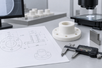
A custom ceramic support begins as a functional need, but the supplier eventually receives a drawing. If that drawing does not communicate the need clearly, a visually correct component may still fit poorly or fail to locate another part as intended. Good drafting translates function into dimensions and acceptance requirements that another team can apply consistently.
For insulating supports, this translation is particularly useful because small geometric features may serve several purposes. A hole can locate a conductor, a shoulder can establish position, and an exposed surface can influence the arrangement of the assembly. Each should be specified according to its role rather than habit.
Explain the component’s function first
Before detailing the part, describe what it supports and how it is installed. Share an assembly view when available. The supplier can then understand why certain surfaces matter and ask informed questions about geometry. A detached drawing without context can make every feature appear equally important.
When specifying Silicate ceramics, include the intended material designation if it has been selected. If material selection remains open, say so and provide the operating requirements. This keeps a preliminary drawing from presenting an unresolved choice as a final instruction. The eventual release should identify both the approved geometry and material clearly.
Establish the locating surfaces
Identify the surfaces that position the support within the assembly. These provide the basis for relevant dimensional relationships and inspection. A useful datum scheme should reflect how the part functions and can be measured, rather than simply choosing the largest faces because they are convenient to draw.
Discuss the proposed scheme with the supplier and inspection team. If the functional surface is difficult to access during measurement, the drawing may need a practical verification approach. Agreement at this stage reduces the chance that a supplier and customer judge the same part using different interpretations of its position and geometry.
Assign tolerances according to purpose
Not every dimension requires the same level of control. A feature that establishes conductor location may need closer attention than an exterior surface that only clears an enclosure. Distinguishing these requirements helps focus manufacturing and inspection effort where it contributes to performance.
Avoid tightening every tolerance in response to uncertainty. Explain the assembly requirement and ask what production can reliably achieve. A tolerance should emerge from the necessary fit and manufacturing discussion. Excessive precision can add cost while leaving the real problem unresolved if the dimension was not connected to the functional interface.
Describe edges and surfaces deliberately
Edges matter during handling and contact, but a general note may not communicate which ones deserve special attention. Identify the edges adjacent to conductors, locating features, or seating faces when their condition affects function. Specify the relevant acceptance requirement through the agreed drawing conventions and inspection method.
Surface appearance also needs context. A support may have areas where finish matters to contact and others where normal manufacturing variation is acceptable. Explain the distinction instead of relying on a sample photograph as the complete standard. Photographs can supplement a specification, but lighting and viewing angle make them an unreliable substitute for defined criteria.
Make holes and slots understandable
A hole intended for clearance has a different role from one intended to position another component. State the necessary relationship through dimensions and tolerances. For slots, consider how the supported part enters and whether the assembly sequence requires extra access. A digital model can conceal a practical installation problem if the parts are only shown in their final positions.
Review internal corners and feature transitions with the supplier. The manufacturing route may influence which details are practical. Where a change is proposed, evaluate whether it preserves the support’s function and the relevant assembly requirements. Supplier feedback is most useful when the design team explains what the feature must accomplish.
Complete the inspection and revision record
A production drawing should indicate its revision and link to the approved part identity. Keep changes traceable to the reason they were made. If a dimension changes after a trial, record whether the change addresses fit, assembly, or another requirement. This allows later teams to understand which evidence supports the released design.
Agree on the checks needed for initial approval and repeat supply. Where an acceptance decision depends on a functional assembly check, explain that clearly. Do not assume that measuring every dimension answers every performance question. Drawing inspection and application verification complement each other, and the quality plan should preserve that distinction.
A useful ceramic support drawing communicates why the part has its shape and how its suitability will be judged. Functional surfaces, purposeful tolerances, clear material status, and practical inspection make the document easier to use. This reduces avoidable clarification and helps turn a custom design into a consistently supplied component.